+86 18501566670
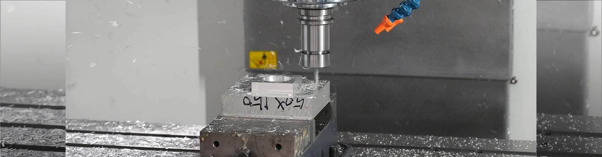
What Are the 7 Common Machining Processes in Mechanical Manufacturing?
 Time:2026-05-22
  Visits:225
An effective mechanical process engineer must also be a proficient application engineer for machining equipment. Such an individual possesses a precise and comprehensive understanding of the various types of machining equipment within the mechanical industry—including their applicable processing ranges, structural characteristics, and machining precision. Furthermore, they are capable of practically integrating this knowledge with the specific equipment inventory of their own company to rationally plan and arrange equipment layouts for diverse parts and processes. They clearly recognize their company's machining strengths as well as its weaknesses, enabling them to effectively leverage those strengths while mitigating the weaknesses to comprehensively coordinate the company's mechanical machining operations.
In the following sections, we will conduct a general analysis and overview of several types of machining equipment commonly utilized in the mechanical processing industry. Our aim is to provide an intuitive yet relatively clear and distinct conceptual definition of the equipment within this sector. Concurrently, we will undertake a theoretical dissection of these various machines to better integrate theory with practice in our future work, thereby providing guidance and support to enhance our professional performance.
Our discussion will unfold in stages, focusing on the most universal machining processes in the mechanical industry: turning, milling, planing, grinding, boring, drilling, and wire cutting. We will provide detailed elaborations on the specific types, applicable ranges, structural features, and machining precision associated with each category of equipment. Let us now proceed to the main subject.
1. Lathes
(1) Types of Lathes: Lathes come in a vast array of types; according to statistics cited in a *Handbook for Mechanical Process Engineers*, there are as many as 77 distinct varieties. Typical major categories include: instrument lathes, single-spindle automatic lathes, multi-spindle automatic or semi-automatic lathes, turret lathes, crankshaft and camshaft lathes, vertical lathes, floor-type and horizontal lathes, copying (tracer) lathes, multi-tool lathes, wheel-and-axle lathes, roll-turning lathes, gear-hobbing lathes, and many others. These major categories are further subdivided into numerous smaller classifications, the sheer number of which is extensive. However, the types most frequently encountered in our mechanical industry are vertical lathes and horizontal lathes; indeed, one can find these two types of lathes in almost any facility where mechanical machining takes place.
(2) Applicable Machining Ranges of Lathes: We will select several representative types of lathes to illustrate the specific machining applications and operational ranges for which they are suited. A. Horizontal Lathes: These machines are suitable for turning external and internal cylindrical surfaces, conical surfaces, contoured surfaces of revolution, and annular grooves. They can also be used for facing operations, cutting various types of threads, and performing processes such as drilling, boring, reaming, tapping, die threading, and knurling. Although standard horizontal lathes feature a relatively low degree of automation and involve significant auxiliary time during processing, their extensive machining range and excellent versatility have led to their widespread application and popularity within the mechanical processing industry. They stand as one of the most representative types of machining equipment in our mechanical sector—indeed, an indispensable asset to the industry.
B. Vertical Lathes: These machines are suitable for machining various types of frames and housing-like components. They are also utilized for processing the internal and external cylindrical surfaces, conical surfaces, end faces, and grooves of various parts, as well as for cutoff operations, drilling, boring, and reaming. Furthermore, with the aid of auxiliary attachments, they can perform additional processes such as thread cutting, facing, contouring, milling, and grinding.
(3) Machining Accuracy of Lathes: A. The typical machining accuracy for standard horizontal lathes is as follows: Roundness: 0.015 mm; Cylindricity: 0.02 mm per 150 mm length; Flatness: 0.02 mm per Ø150 mm diameter; Surface Roughness: 1.6 Ra (μm).
B. The machining accuracy for vertical lathes is as follows: Roundness: 0.02 mm; Cylindricity: 0.01 mm; Flatness: 0.03 mm. The aforementioned accuracy values serve merely as relative benchmarks and do not imply that every single lathe will conform to these exact figures. Many lathe units exhibit a certain degree of upward or downward fluctuation in accuracy, depending on the specific manufacturing specifications and assembly conditions established by the manufacturer. However, regardless of the magnitude of this fluctuation, the resulting machining accuracy must invariably meet the requirements stipulated by national standards for this category of equipment. Consequently, if—at the time of purchase—the machining accuracy of such equipment fails to satisfy the requirements set forth by national standards, the purchasing party retains the right to refuse acceptance of the equipment and withhold payment. 2. Milling Machines
(1) Types of Milling Machines: The variety and complexity of milling machines are extensive. According to statistics found in a *Handbook for Machining Process Engineers*, there are over 70 distinct types. Typical major categories include: instrument milling machines, knee-and-ram type milling machines, gantry milling machines, surface milling machines, copy milling machines, vertical knee-type milling machines, horizontal knee-type milling machines, bed-type milling machines, toolroom milling machines, and others. These categories are further subdivided into numerous smaller classifications, the sheer number of which is too vast to list exhaustively. However, within the mechanical manufacturing industry, the most commonly utilized types are the Vertical Machining Center and the Gantry Machining Center. These two types of milling machines can be found in almost any facility engaged in mechanical processing. We will therefore focus on these two representative types to provide a general introduction and analysis.
(2) Machining Applications of Milling Machines: Given the immense variety of types and structural configurations among milling machines—and the significant differences in their scope of application—we will limit our discussion of machining capabilities to the two typical types currently in widest use: the Vertical Machining Center and the Gantry Machining Center.
A. Vertical Machining Center (as shown in the figure above): A Vertical Machining Center is, in essence, a vertical CNC milling machine equipped with an automatic tool changer (tool magazine). Its primary characteristic is the use of multi-edge rotary cutting tools to perform machining operations. It is capable of processing flat surfaces, grooves, indexed parts, helical surfaces, and various complex curved surfaces. Notably, with the advent and application of CNC technology, the machining capabilities of this type of machine tool have been significantly enhanced. In addition to performing various milling operations, it can execute compound machining tasks—such as drilling, boring, reaming, and tapping—on a workpiece, thereby demonstrating immense practical utility and widespread applicability. B. Gantry Machining Centers: Compared to vertical machining centers, a gantry machining center represents a hybrid application—essentially a CNC gantry milling machine integrated with a tool magazine. In terms of processing scope, gantry machining centers possess nearly all the machining capabilities of standard vertical machining centers; moreover, regarding part dimensions, they are capable of accommodating the machining of much larger workpieces. Furthermore, they offer significant advantages in both machining efficiency and precision. This is particularly evident in the practical application of 5-axis simultaneous gantry machining centers, where the machining scope has been vastly expanded, thereby laying a solid foundation for the advancement of my country's manufacturing industry toward high-precision and cutting-edge technologies.
(3) Machining Precision of Milling Machines: A. Vertical Machining Centers: Flatness: 0.025/300mm; Surface Roughness: 1.6 Ra/μm. B. Gantry Machining Centers: Flatness: 0.025/300mm; Surface Roughness: 2.5 Ra/μm. The aforementioned precision values serve merely as relative reference points and do not imply that every single milling machine will conform to them exactly. Many milling machines exhibit a certain degree of upward or downward fluctuation in precision, depending on the specific requirements of the manufacturer and the particular assembly conditions. However, regardless of the magnitude of this fluctuation, the resulting machining precision values must invariably meet the requirements stipulated by national standards for this category of equipment. If, at the time of purchase, the machining precision of such equipment fails to meet national standard requirements, the purchasing party retains the right to refuse acceptance and withhold payment.
3. Planers
(1) Types of Planers: Compared to lathes and milling machines, the variety of planers is significantly more limited. According to statistics compiled in the *Machining Process Engineer's Handbook*, there are approximately 21 distinct types. Typical examples include cantilever planers, gantry planers, shaper-planers (shapers), edge planers, and die planers. These broad categories are further subdivided into numerous specific models. Among them, the types most frequently utilized and widely adopted within the mechanical manufacturing industry are the shaper-planer and the gantry planer. As illustrated in the figure above, we will now proceed to provide a basic analysis and introduction focusing specifically on these two representative types of planers. (2) *Scope of Application for Planers:* The planing motion of a planer primarily consists of a periodic, reciprocating linear movement relative to the workpiece. It is typically suited for machining features such as flat surfaces, inclined planes, and concave or convex surfaces; it can also be used to machine various curved surfaces. However, due to inherent limitations in its machining characteristics, the cutting speed is relatively low. Furthermore, the cutting tool does not engage in material removal during the return stroke, resulting in "idle stroke" losses and, consequently, relatively low machining efficiency.
Concurrently, with the immense technological advancements in the CNC and automation capabilities of other types of machining equipment, the planing process is now on the verge of being phased out. Judging by current trends in equipment upgrades, this specific type of machine tool has not undergone significant innovation; to a large extent, it remains anchored to its original structural designs and layouts. In particular, the rapid development of vertical and gantry machining centers—coupled with continuous innovations in cutting tools—has largely supplanted the planer's advantages in terms of machining scope, leaving this relatively inefficient class of equipment in a rather precarious position.
(3) *Machining Accuracy of Planers:* The machining accuracy achievable through planing generally falls within the IT10 to IT7 tolerance grades. Notably, for the machining of long guide surfaces on large-scale machine tools, planing can even serve as a substitute for grinding—a technique known as "precision planing replacing precision grinding."
4. Grinding Machines
(1) *Types of Grinding Machines:* Compared to the previously discussed types of machining equipment, the variety of grinding machines is far more extensive. According to statistics found in a handbook for mechanical machining technologists, there are approximately 194 distinct types. Broadly categorized, they include: instrument grinding machines, external cylindrical grinding machines, internal cylindrical grinding machines, bench grinders, coordinate grinding machines, guide-way grinding machines, tool sharpening machines, surface and face grinding machines, specialized grinders for crankshafts, camshafts, splines, and rolling mill rolls, universal tool grinders, super-finishing machines, internal honing machines, external and general-purpose honing machines, polishing machines, and abrasive belt polishing and grinding machines. Grinding machines encompass a wide array of types, including tool and cutter grinders, machines for grinding indexable inserts, lapping machines, groove grinders for ball bearing rings, raceway grinders for roller bearing rings, superfinishing machines for bearing rings, blade grinders, machines for processing rollers and steel balls, grinders for valves, pistons, and piston rings, as well as machines for refinishing automotive and tractor components. Given the vast scope of grinding machine classifications and applications—many of which involve highly specialized equipment tailored to specific industries—we will focus our basic introduction exclusively on those grinders that enjoy widespread utility within the general mechanical manufacturing sector. In this article, we have primarily selected cylindrical grinders and surface grinders to provide a brief overview.
(2) Scope of Application for Grinding Machines: A. Cylindrical Grinders—These machines are primarily designed for machining cylindrical surfaces, conical surfaces, the external surfaces of other bodies of revolution, and the end faces of shaft shoulders. Due to their superior processing versatility and precision, they are widely utilized in mechanical manufacturing for the production of high-precision components—particularly during the final finishing stages of these parts. Not only do they serve to maximize the dimensional accuracy of the machined parts, but they also enable the achievement of exacting surface finish requirements; consequently, they constitute an indispensable class of equipment within the mechanical manufacturing workflow.
B. Surface Grinders—These machines are primarily employed for machining flat surfaces, stepped surfaces, side faces, and other planar features on workpieces. They are also extensively used throughout the mechanical manufacturing industry—particularly for the surface finishing of high-precision components—where grinding machines often stand as the definitive choice for ensuring final dimensional accuracy. Precisely for this reason, the operation of surface grinders is considered a mandatory skill for the majority of grinding machine operators; furthermore, in certain equipment assembly sectors, proficiency with surface grinders is regarded as a standard competency for assembly technicians, as the grinding of various adjustment shims required during the assembly process relies entirely upon the capabilities of surface grinders.
(3) Processing Precision of Grinding Machines: A. Processing Precision of Cylindrical Grinders—Roundness and Cylindricity: 0.003 mm; Surface Roughness: 0.32 Ra (μm). B. Machining Precision of Surface Grinders: Parallelism: 0.01/300mm; Surface Roughness: 0.8 Ra (μm). From the aforementioned precision specifications, it is evident that—compared to earlier machining equipment such as lathes, milling machines, and planers—grinders are far more capable of achieving superior geometric tolerance precision and surface finish. Consequently, grinders are widely and universally employed in the finishing stages of many component manufacturing processes.
5. Boring Machines
(1) Types of Boring Machines: Compared to the previously discussed categories of machining equipment, boring machines constitute a relatively specialized niche. According to statistics found in a handbook for mechanical machining technologists, there are approximately 23 distinct types. Broadly categorized, they can be classified into the following groups: deep-hole boring machines, jig boring machines (coordinate boring machines), vertical boring machines, horizontal milling-boring machines, fine boring machines, boring machines for automotive and tractor repair, and others. Among these, the most prevalent and frequently utilized type within the mechanical engineering industry is undoubtedly the jig boring machine. We will now provide a brief introduction to and analysis of the specific characteristics of jig boring machines.
(2) Scope of Application for Boring Machines: While the variety of boring machines is extensive, we will focus our brief introduction on the jig boring machine; readers may then apply this knowledge analogously to understand other types of boring machines. A jig boring machine is a precision machine tool equipped with a precise coordinate positioning system. It is primarily utilized for boring hole systems that demand exceptionally high accuracy regarding size, shape, and positional relationships. It is capable of performing various operations—including drilling, reaming, counterboring, spot-facing, grooving, and surface milling—and can also be employed for coordinate measurement, precision scaling, and scribing tasks, thereby offering a remarkably broad and reliable range of machining capabilities.
However, with the rapid advancement of CNC technology—particularly the vigorous development of CNC vertical and horizontal milling machines—the boring machine, once the undisputed dominant force in the machining of hole systems, now faces the risk of gradual obsolescence. Of course, it retains certain objective characteristics that render it irreplaceable in specific contexts; nevertheless, regardless of whether a specific type of equipment faces decline or undergoes further development, such shifts invariably represent progress for the mechanical machining industry—signifying advancements in technology, manufacturing processes, and, ultimately, our nation's manufacturing sector as a whole. (3) Machining Accuracy of Boring Machines: The diameter accuracy of holes machined on coordinate boring machines typically falls within the IT6–IT7 tolerance grades, with a surface roughness of 0.4–0.8 Ra/µm. However, boring operations suffer from a significant drawback—particularly when machining cast iron parts—namely, the sheer mess involved. A person walking in looking like a refined scholar might emerge resembling a rough-and-tumble warrior; one is left feeling utterly unrecognizable after operating a boring machine. Consequently, given the practical realities of this specific machining process, the likelihood of this type of equipment being superseded in the future is increasing—after all, who doesn't care about their personal appearance? Even if many of us aren't exactly lookers, we still feel the need to at least *act* as if we are!
6. Drilling Machines
(1) Types of Drilling Machines: This constitutes the most widely utilized type of machining equipment in the mechanical engineering industry. Virtually every mechanical processing plant possesses at least one; indeed, if you lack even this basic piece of equipment, you would be too embarrassed to claim that you are in the machining business. According to statistics found in a standard *Machining Process Engineer's Handbook*, there are approximately 38 different varieties of drilling machines. Broadly categorized, they can be classified into the following types: coordinate boring-drilling machines, deep-hole drilling machines, radial drilling machines, bench-type drilling machines, upright drilling machines, horizontal drilling machines, milling-drilling machines, center-hole drilling machines, and so on. Among these, the *radial drilling machine* is the most ubiquitous within our industry; it is essentially the standard-issue equipment for mechanical processing shops—without it, you simply cannot operate in this field. Precisely for this reason, we will now focus specifically on introducing this particular type of drilling machine.
(2) Scope of Application for Drilling Machines: We will primarily address this point with reference to the radial drilling machine. Regarding this specific machine tool, I can sum it up in a single phrase: it is used to drill various types of holes. In addition to basic drilling, it can also be utilized for operations such as hole enlarging (boring), reaming, counterboring, and thread tapping. However, it suffers from one major shortcoming: its positional accuracy regarding hole patterns is relatively low. Consequently, for parts requiring high precision in the positioning of hole patterns, we typically do not select a drilling machine to perform the task.
(3) Machining Accuracy of Drilling Machines: Generally speaking, there is virtually no "machining accuracy" to speak of in this context; the machine's sole function is simply to drill a hole. 7. Wire Cutting
As I have had limited exposure to wire cutting equipment, I have not accumulated significant experience or conducted extensive research in this specific area. Consequently, my understanding of its broad application within the mechanical industry is somewhat limited. Nevertheless, this processing method retains a unique value, offering distinct advantages—particularly for the blanking and machining of irregularly shaped parts. However, given its inherently low processing efficiency and the rapid advancements in laser technology, wire cutting equipment is gradually drifting toward the periphery of the industry, facing the looming threat of obsolescence.